Abstract
The report is a dedication to the analysis of the main production of Advanced Electronics Company, which is also called AEC. The main specialization of the company is manufacturing military electronic devices. In that regard, the main purpose of the report is to analyze and assess the main products of the company (electronic devices, TADS/PNVS) and the effectiveness of their application in those spheres. Another goal of the research is to evaluate the necessity to provide the training courses for the company employers thus introducing different types of testing programs and procedures. All these steps are taken to improve the image of the company and to increase its competitiveness. In the report, such methods as descriptive analysis have been used and qualitative assessment of the efficacy of the electronic devices. In particular, such mobile device as TADS/PNVS has been described and subjected to the necessity to be tested by function, in-circuit, and continuity tests, At the end of the training course, it has been determined that different testing programs and procedures have a different level of effectiveness and, therefore, they should be applied in different spheres. On a whole, the research is of considerable value for the company’s improvement and further development, as the introduction of those designs will foster the introduction of this company to the international market. Finally, this report reveals much space for further investigation in this field of electronic technologies.
Introduction
Overview of the Company. Advanced Electronics Company also known as AEC is one of the most popular companies in the military sphere in Saudi Arabia. Even more, this organization is the only one that is approved in the country to develop relations with such companies like the Royal Saudi Land Forces, the Navy, Saudi Armed Forces, Raytheon, Northrop Grumman, etc. AEC was established in September 1988 and presented as the Saudi Economic Offset Program company with a variety of purposes like the creation of local capacities and the development of communication systems. Within a short period AEC has become a leading manufacturing company. Its numerous attempts to achieve the necessary position and have the possibility to use strategic areas and enhance the Kingdom’s sufficiency turned out to be successful and rather effective. However, like any other fast-developing company, AEC faced certain problems and challenges during the process of its improvement.
Unpredictable limitations of the Military Systems appeared at the beginning of 1990. Difficulties with repairing and testing the necessary electronic equipment bothered the representatives of AEC and promoted the development of other obligatory systems. Such systems were offered in 1995 (Telecom Systems) and in 2002 (Industrial Programs). The main purpose of these programs is to improve as many fields of work as possible and to create the possibility for a new system’s representation. As a result of this work and demands, Information and Communication Technologies (ICT) were introduced in 2005.
Constant work of AEC representatives and the purposes to become famous and recognizable in the whole world have already made AEC one of the biggest companies in Saudi Arabia, whose purposes are to design, upgrade, and support the development of Electronic Products and to promote the use of these products among different military, industrial, and technological customers.
In general, there are three spheres, AEC deals with: military, industrial, and telecommunications. In each industry, a certain number of customers are already present, but this organization aims to develop these relations and have more constant customers all over the world.
E & D. AEC is considered to be a complex organization of departments, where each department is responsible for a certain amount of work. Each department performs certain functions, and the outcomes of their work become influential for each other. One of the departments that perform probably the most important function in the company is the E&D Department. E&D is the shortened form of the Engineering and Development Department. This department is regarded to be a kind of spinal column for AEC.
E&D functions as the body to guarantee significant improvements for the company and the development of the necessary technologies to meet the demands of constant and new customers. It is very difficult to become noticeable in the world arena and be able to cope with numerous competitive organizations and settled prices. This is why E&D focuses on the ideas on how to present the most effective solutions to the existed problems and challenges and offer the most appropriate prices for customers to attract their attention.
The significance of this department is proved due to constant investing. The already formed engineering team enlarge personal level of knowledge and try to be prepared to develop new services and goods. The variety of their E&D functions is impressive indeed: (1) constantly present industrial products and solutions; (2) develop security systems; (3) work on necessary industrial automation; and (4) promote improvement of monitoring systems.
ERC. Another important department in AEC is the Electronics Repair Centre (ERC). It is established from the main buildings of AEC to support the development of AEC services and goods from different perspectives. Its objective is to provide customers with support in a short period of time and be able to test and repair equipment of military and commercial spheres.
There are two main units in this center: Electronic Repair Operation (ERO) is dedicated to pure electronic products and systems that have to be repaired and Technical Services (TS) are responsible for proper promotion of services and products to satisfy customers. Taking into consideration this fact, general and informative definition of the ERC may be presented. The ERC is the department that aims at providing the fastest and the best possible support and services for its customers and setting the lowest costs to attract customers and make sure to use these services again.
The ERC unlike other departments of AEC focuses on customers’ services and satisfaction only. Its experience is closely connected to the sphere of repairing in accordance with settled demands and technologies. It is very important to meet the requirements of the present times, this is why the ERC has to evaluate the current state of affairs and match them with customers’ demands and available opportunities. Such services like training, consultation, and explanation of unclear points become another integral part of the ERC work.
The fact that the company under discussion deals with three spheres allows admitting that the ERC and its repairing projects are carried out in all military, industrial, and telecommunications sectors. The main peculiarities of the ERC facility are the environmentally controlled equipment, government clearness, and properly arranged security system. If a mistake is made during the repairing processor tests, the abilities of the ERC need to allow the necessary changes and improvements. The presence of such a department in AEC demonstrates how careful and considered attitude of the company to its customers and to the quality of the services provided. It is not always obligatory to present enough qualified products and services, but it is extremely important to be able to present support in time and to repair everything accordingly.
Work Supervisor
During the process of writing this report and the whole program, Mr. Eyad Kassab was my supervisor. His experience, background knowledge, abilities, and desire to help and explain turned out to be rather important for my work. 4 years of practice became really helpful and significant in my life. This person taught numerous lessons in order to provide me with the necessary knowledge and understanding of the subject. With the help of his suggestions and hints, I have all chances to continue my work in this organization and become an important worker. Graduation from the university is the period when many decisions have to be made, and this person encourages me to choose this profession and become a professional like he is. It is never too late to enlarge personal knowledge and skills, and this practice shows how it is possible to improve personal attitude to work and duties.
Eds Training Course
Why Is ESD Important? In order to realize the importance of the EDS training course, it is necessary to analyze the essence of AEC work and its purposes and explain why this work has to be checked and how it may be improved. First of all, it is necessary to admit that AEC is a fast-developing company in electronics industry. To prove its good reputation of the company that takes care of its customers and produces qualified services and goods, AEC should correspond to two main points: high standard manufactures and properly trained employees, who are always eager to improve personal work and do everything possible to achieve the best results only.
Electronics industry is constantly changing sphere, where current accomplishments and innovations have to be taken into consideration, this is why when the time to deal with electronic devices comes, it is better to know their peculiarities and features and not make mistakes. Sensitive equipment may be damaged because of wrong usage or lack of knowledge. And much time needs to be spent to repair this equipment; and if a company has a chance to pass through the necessary training, this company should use this chance.
For such reasons, the necessity of the ESD courses for the employees of AEC turns out to be evident. Those people, who deal with sensitive devices, need to pass this training and get a clear understanding of what steps have to be taken, and which ones may lead to negative outcomes, and which ones are better to take in order to succeed in the chosen work. Problems with electronic technologies are numerous in their numbers, and their number increases with time because of technological progress. So that ESD course training becomes an important part of AEC work.
What Is ESD? So what is the essence of ESD course training? What does ESD mean in reality? What do employees need to be ready for when they agree to pass through this training?
ESD or Electro Static Discharge is a short electric current that happens between the objects which have various electrical potentials. It is a kind of spark that is caused by the appeared direct contact within one electrostatic field. If the process of electrostatic discharge goes wrong, the failure of devices in electronics industry happens. One of such failures is integrated circuits that are developed due to high voltages. The result of this failure is the appearance of antistatic devices which aim at preventing static procedures.
AEC pays certain attention to the work of each employee and tries to protect each product and service from possible damage that is possible to predict. All electronic devices and materials need to be treated in accordance with the established rules and under the appropriate conditions. With time, the representatives of AEC make a successful attempt to define the purposes of ESD and clear up its characteristics. First, ESD should provide employees with the necessary training and certificates that demonstrate employees’ maturity and abilities to work with sensitive devices. Second, ESD is maintained by the proper equipment with the necessary certification. And finally, static control measures are applied constantly in order to consider possible changes and new requirements.
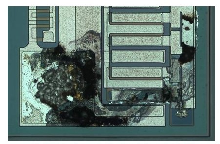
The peculiar feature of ESD and its effects on goods is connected to the number of volts that are felt by a person and by a device. For example, a person can feel 2 000 V or even more; and a sensitive device, in its turn, may be easily damaged and burned with 20 V only. This is why the necessity to test due to ESD depends on both the device’s sensitivity and human reactions. It is necessary to control this problem in order to avoid constant damages and problems that have an impact on sensitive devices. The results of inability to control electric currents may lead to unpredictable results and the necessity to develop a new well. In the Figure 1, the example of how an electronic device may be damaged due to ESD is presented.
Causes of ESD. There are several issues that cause ESD, and some of them need to be investigated by the representatives of AEC to protect their projects and not to disappoint customers. Usually, ESD is caused by people and their activities. Improper grounding, poor connection between subjects, and wrong level of humidity – all this may lead to other serious problems and products damage.
The first important cause of ESD that has to be mentioned is static electricity or tribocharging. It is the process when the contact of two objects leads to separation of electric charges. Its best example is the rubbing of plastic pens against dry hair. Different electric potential appears and leads to ESD events and further problems.
Another powerful cause of ESD happens because of electrostatic induction that happens when one electrically charged thing is close to a conductive thing that has no grounds. Electrical charges between objects cannot be controlled all the time, this is why it is evident that another type of problem that influences the quality of an object appears. During the process of electrostatic induction, charge redistribution takes place within two bodies and polarization of unconducting bodies develops. The results of such a process may be observed in the Figure 2:
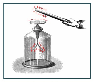
Of course, this example can hardly be applied to the devices used by AEC but still it helps to comprehend the cause of why so many products are damaged within a short period of time and without clear reasons and grounds.
For people, who deal with electronics all the time, it is hard to take the necessary measurements and follow the rules of the time. This is why solid background about the causes of ESD and its effects on people and their work with sensitive devices should help to avoid troubles and repairing. Electro Statistic Discharge is a serious problem for the employees of AEC, this is why its control remains to be improved constantly.
How to Prevent ESD. Now, it is high time to talk about the steps that have to be taken in order to prevent ESD and damages of products, caused by ESD. By being aware of how the main cause of ESD, static electricity, happens, it becomes easier to take the necessary precautions.
The most evident ways that may prevent ESD damage are:
- Antistatic wrist straps (Figure 3) ground a person, who deals with electronic devices. It is connected to the ground by means of a coiled cable and megaohm resistor. Wearing such wrist straps promotes the safe discharge a person may accumulate.
- Absence of bracelets and rings prevents spark creation.
- Antistatic bags also help to prevent sensitive devices from damage.
- ESD jackets (Figure 4) represent a kind of static shielding for people, who deal with electronic devices and are under a threat of being disturbed because of electric charges.
- Presence of dust also influences ESD and promotes static electricity. It is obligatory to make working places clean and decrease the amounts of dust day by day.


Such simple but still effective steps need to be used by any employee of AEC. These ESD course training promote safe work and more effective results: abilities to produce more products, to follow all the necessary requirements, to meet the established results, and to correspond to the customers’ expectations. The work of technicians is not easy, and additional protection like wrist straps and ESD jackets does not require too much efforts and time. In case these measurements are broken, the results may become negative for the company and people.
Each point that was mentioned above to protect a person and a device has its own functions. And only when all points are taken into consideration, safe work is possible. It is useless to wear antistatic wrist straps but forget to wear a jacket or to wear as much bijouterie as possible. In this case, a person is protected from one side and, at the same time, this person becomes available for some damage from another side.
AEC has many functions and missions to be completed. Its purposes and influence on the world market are improved day by day. This is why all protection measures have to be followed thoroughly and kept in mind all the time.
TADS/PNVS
Another sphere of the AEC production is closely connected with military projects and programs aimed at modernizing and supporting local military requirements for electronic maintenance and repair. Military Systems Business Unit (MMBU0) that cooperates with respectable international OEM carries out the production of navigation night systems for helicopters. The production of TADS/PNVS encompasses a huge domain of the company’s output, which has been tested and inspected by AEC at the component level.
The Target Acquisition and Designation Sight/Pilot Night Vision Sensor(System) is a device engineered for an AH-64 Apache helicopter.

TADS consists of two independent systems. The first one functions as a targeting system enhancing the reliability and reducing the obsolescence of the Apache Army Helicopter Mark 1. TADS consists of the following parts:
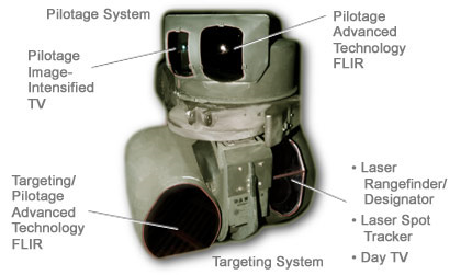
- Electro-optical sensors (direct view optic and optical relay tube). Laser rangefinder is used for determining the distance to an object. The principle of work lies in sending a laser impulse towards the object; this device can also measure the time required for pulse reflecting from the target and returning. Laser rangefinders are highly used in the military, as they provide an exact distance to objects located far beyond the distance of shooting.
- Laser target designator is for laser-navigated missiles
- TV camera (pilotage image intensifier): this component consists of daylight and night TV camera that is slaved to the head movement of the pilot
- Laser spot tracker
- Pilotage advanced technology (a forward-looking infrared image that allows identifying objects in the nighttime).
The optimal rotation of TADs is 120 degrees in azimuth and +30/-60 degrees in elevation. TADS can change its direction independently of Pilot Night Vision Sensor. TADS movements can be subjected to basic movements of the crewmember to the edge of the vision radius. This device also allows projecting the images on the helmet-mounted display from TADS. Those images overlay the pilots’ vision of the cockpit and battlespace. TADS contains an infrared sensor with thermal imaging system and monochrome daylight camera that is planned to substitute it with the full-color camera. This device should also comprise direct view optics for the copilot to see via the Optical Relay Tube. Direct vision optics serve to enhance daylight target recognition. An optical relay tube is aimed at transmitting the direct vision optics to clock-pulse generator. However, the recent models of this AEC have not inserted this apparatus because it is rarely used and, therefore it has been removed and substituted by a Multi-Purpose Display.
PNVS is installed above the TADS and includes an infrared camera subjected to the head movement of the crewmembers. This device can rotate about 90 degrees in azimuth; in elevation, it is about +30/-45 degrees. The speed of PNVS rotation movement is rather high and constitutes about 120 degrees per second. These movements are accurately subjected to the head movements of the crewmember.
The combination of PNVS and TADS capabilities provides Apache H-64 with a potent system and enhances its reliability and durability during air attacks. Therefore, these two integrated systems containing two separate elements are located on the nose of the cockpit. Additionally, TADS/PNVS device also includes laser guidance that considerably increases target tracking.
The device under consideration is still in the process of development so that it still requires improvement and a combination of tests and experiments. The process of testing is of considerable importance for the product to be improved and modernized so that each type of test considers only one aspect of navigation system performance.
Function Test
Function test, which is also called integration test, is the first test that should be held by the company during the release of a particular product. This is an effective and powerful testing approach, which can significantly decrease the number of undetected defects. The main goal of the function test is to evaluate functional parts of the system. The test also serves to verify whether the system performance is at the appropriate level. The analysis of each component is fulfilled according to the specifications. The main requirement of the function test lies in the capability that must be provided by the components. The external user of the system should follow this requirement.
The process of function testing presupposes the fulfillment of subsequent operations: functional decomposition, verification, test case design, traceability, and test case execution.
Functional partitioning of the apparatus is the division of a system into functional parts and areas. Hence, it is important to remember that the tested device (TADS/PNVS) needs to be split into two components: target acquisition designation system and pilot night vision sensor. The first system generally includes laser optical devices whose major function is to target and navigate. The second components directly relate to the behavior of the external user. Here, it is necessary to check the reliability of functions. Functional decomposition will help to define the performance of these two devices independently.
Verification is the next stage of the function test consisting of the functional specification of each component. This test is aimed at determining the concept of each software component. The Advanced Electronics Company needs this test to accomplish the function test. However, it should be stressed that if the testing team cannot provide the company with the testing requirements then it is necessary to create its own set of tests. These requirements should be systemized according to functional decomposition.
Test case design serves to ratify the product performance in accordance with the previous set of requirements. The cases should be also systemized and itemized taking into consideration the relevant functional partitioning.
The traceability stage suggests that test cases need to be referred to the appropriate requirement. Once all issues of a requirement have been verified by the tests, then the function test can be considered as fulfilled. Considering the company specialization, it is necessary to emphasize the importance of those tests, as this device is still referred to as recent technological achievement being at the stage of development.
All the stages of the function test should be executed properly and the results need to be recorded. Therefore, test case execution stage should define the content of the Test Plan recording each stage of testing. In case, the current phase of the application fails to support the testing or one of the requirements, then this testing should be postponed until all the requirements conform to the test.
Once again, AEC should take this test seriously to provide a high-quality product and be competent with other companies specializing in the production of military technologies. The main advantage of function testing lies in the analysis of the product effectiveness through functional decomposition.
The peculiarity and importance of the function test lie in consideration of TADS/PNVS performance in practice, as the test presupposes the analysis of functional behavior of each component. The disadvantage of the function test consists in lack of performance analysis of components as a whole. It should be also admitted that there should be a strict observance of the subsequence of stages, as each one depends on another.
In-Circuit Test
The in-circuit test is a type of electric probe testing that checks for opens, shorts, resistance and other basic quantities to show whether the entire device was correctly constructed. The in-circuit test may be carried out with the help of bed of nails testing including fixture test equipment with fixtureless in-circuit setup. The scope of the test lies in checking the efficiency and reliability of the contact points between the tested device and in-circuit test resources.
While checking any technological device, there is an urgent necessity to check the board density. Therefore, this test must be included in the testing program of the company to guarantee a high-quality product.
The main peculiarity of this test lies in the analysis of TADS/PNVS performance as an integral device. In-circuit testing encompasses arrange of consistent operations. Hence, the main stages include:
- Electrolytic capacitor discharging that is carried for safety purposes;
- Shorts and opens testing;
- Testing of analog components for an adequate assessment of all components;
- Photodetectors to test direct view optics and infrared camera with thermal images system installed on the nose of the helicopter.
- Software and digital components testing;
- As TADS/PNVS is considered as external equipment, it is also necessary to apply hi-voltage measurement.
- Joint Test Action Group testing: the company needs to create a special testing department with competent group of professionals.
To fulfill in-circuit test successfully, it is necessary to apply specific in-circuit testers that propose different software test platforms. There are two parts of in-circuit test equipment: the tester itself consists of a matrix of sensors and drivers and fixtures. The tester may contain about a thousand sensor points (nodes) that are adjusted to the fixture.
Again, it is obligatory to emphasize the importance of this test due to the increasing board complexity. In-circuit testing also needs to be continuously improved. The advanced in-circuit testing should be able to surpass the problem of increasing speed and to identify the components defects thus referring to pin device level. Moreover, the operation can be accomplished automatically from the circuit files; the information can also change manually.
The major limitation of this testing program lies in the fact that it cannot offer a complete check of all functions of the device. Another problem is limited access to the sensor points (nodes) so that it is often difficult to connect them with the board. Nonetheless, boards have become more compact so that there is no possibility to find pads for the nodes. As it can be viewed, there is a number of advantages of in-circuit testing; still, the contracted component sizes have aggravated the access to the drive sensors on boards. The fault coverage of the in-circuit test is relatively high in case there is access to all the nodes on the board.
The test will be of great practical importance for the Advanced Electronics, as their product range is not limited by the military technologies. In this particular case, the navigation system can be checked for the accuracy of target defining and object identification. In addition, in-circuit testing permits examining laser rangefinder capabilities and laser spot tracker effectiveness.
Integrated Circuit Test
Integrated circuit test engineering is closely connected with activities carried out within electronic circuit advancement process. The increasing role of test engineering, therefore, leads to a growing necessity to develop skills within a technology development team. This is especially important for AEC whose especially specialization is narrowed to producing digital technologies. The integration of test activities, fabrication, and design is the only way out to ensure that a design issue correlates with the quality and practical application.
Testing process should be held to provide a wide range of equipment for systematic operations. This particular type of testing is, perhaps, the most modernized one investigating the isolation capability of laser devices. This is especially important for inspecting laser components of the navigation device consisting of laser rangefinder and laser spot tracker. Hence, the main task of testing includes the check for mixed-signal devices in terms of accuracy and power of reflection.
Integrated circuits consist of active and passive components: transistors, resistors, diodes, and capacitors. Due to their reduced size, the application of integrated circuits can simplify complex systems thus decreasing the number of components. The usage of the circuits can considerably reduce the power consumption and equipment size and, therefore, it can decrease the cost of the entire device. It should be also stressed that an integrated circuit constitutes the inherent part of the night vision navigation device.
It should be mentioned that the automatic test equipment requires preliminary testing, which includes the validation of electrical test parameters. The integrated circuit test is at issue nowadays, due to the rapid development of microelectronic circuits that contain an endless number of transistors. In that regard, it requires numerous test engineering activities during production and development.
Integrated circuit testing requires an alternative testing approach that excludes the application of vacuum tubes, as it is rather difficult to unsolder the part of the circuit. There are several consistent stages for testing to be held successfully. First, the circuit needs to be tested electronically to indicate its operational characteristics and compare them with recorded characteristics of the device. Once the characterization is completed, the product is ready to go to fabrication.
Like other electronic devices, TADS/PNVS should be subjected to computer design, which has also capability to test digital and mixed-signal devices. What is important is waterproof testing, as the navigator is located on the external part of the helicopter, which is always subjected to the weather phenomena.
This test requires the highest level of responsibility, as the integrated circuit is the most important component of the navigation program. Therefore, the company should have all the necessary equipment to conduct full-fledged testing. When conducting the test, it is crucial to find the connection between design and test.
In general integrate circuit testing presupposes a though and ongoing examination of digital technologies thus considering the efficiency and reliability of the device in terms of software effectiveness. Even though this the testing requires enormous expenditure and complicated procedures, it should still be included in the testing program of the company, in case it is focused on preserving a respectable image and delivering a high-quality product.
Continuity Test
A continuity test is also applied in the field of electronics; it provides the checking of an electric circuit by placing a small voltage through the chosen path. Hence, the main purpose of this test is to check whether the circuit is closed or open. If it is open, then the device comprises the damaged components, broken conductors, or excessive resistance.
The continuity test is carried out using multimeters that measure electron flow and continuity testers, a more common device with light bulbs that switch on when current flows. Continuity testers are applied to define the electronic path set between two particular points. The circuit must be completely discharged before connecting it to the device.
The tester contains an indicator with a battery – a source of electrical power – that is activated in case it is established between two test paths. The indicator may be presented as electric light that shows when the circuit is closed. In case the continuity testing is required for high-resistance circuits, it is necessary to use a low current apparatus serving as an amplifier for driving a LED as indicator. The scope of application lies in testing the wires to define two ends that belong to a particular one.
This test is considered one of the cheapest ones, as it requires a minimum of devices. At the same time, it is bound by a number of restrictions due to extreme sensitivity of testing. Therefore, we can refer to this testing as to the obsolete ones due to the prevalence of digital technologies.
Based on the above, the continuity test is not appropriate for a pilot navigation system, as this device belongs to an advanced level of technological development. Due to the fact that TADS/PNVS is a sophisticated digital device that includes laser and optical components, this test will not be enough to check the apparatus efficiency. However, it may serve as a preliminary stage of testing that allows conducting other tests.
Another reason to introduce a continuity test to the testing program lies in the necessity to check for the connection of the navigation system of night vision to the helicopter itself. This integrity of these two hardware is an inherent condition of successful performance TADS/PNVS system, as they are connected by a bundle of wires.
Continuity test is the most conventional method for controlling the efficiency of military devices and, therefore, it must be included in the testing program of Advanced Electronic Company to maintain the image of a reliable company. The necessity of continuity test introduction is also explained by the multifunctional organization of this facility.
Automatic Meter Reading System (AMR)
What is AMR? Automatic meter reading is a technology introduced in order to automatically control data from metering devices without personally checking each physical location of the devices. All the data are collected and analyzed in terms of billing and troubleshooting. Originally, meter reading devices were used only to collect data electronically and match results with accounts. However, modern inventions presuppose usage of the latest technologies to facilitate the operation of automatic meter reading devices. This device is based on the AEC digital electronic energy meters in order to serve key-account customers. The automatic reading meter device combines characteristics of several systems used for collection, troubleshooting, billing, and storing data from electronic meters.
The design of the automatic meter reading device presupposes advantages that include reliability, upgradeability, interoperability, scalability, and maintainability. All these features facilitate the installation, operation, and maintenance of the device. Customers benefit from automatic meter reading devices because they do not have to worry about billing statements; improved procedure of billing and storing allows the operators not to check physical locations of the devices. The reduction of the manual operation, readings, and billings leave no space for errors. All improvements are aimed at increasing accuracy of the device; access to the property of the customers should not be gained because all processes do not require manual operation. Customers are sure to benefit from using the automatic meter reading devices because it reduces costs as well as improves payment processing. The reliability of the device can be characterized by leakage tests that detect any tamper and leakage at an early stage.
As the automatic meter reading device presupposes that the process of collecting and storing data, billing, troubleshooting, and maintaining the device should be automatic, it means that electronic maintenance is substituted for physical operation. This process presupposes an electronic device that transmits the data from the storage and collection physical location into the electronic database. The interfaces for automatic meter reading devices vary with a view to the way of data transmitting.
Pulse Interface. The first interface that should be considered is a pulse interface. Its operation presupposes that a signal from the pulse module and another signal from the digital module are transmitted to the machine interface unit which then transmits it into the concentrator. After this, the signal is transmitted to the router which distributes it between the computers connected to the electronic database. It is necessary to mention that the pulse interface has its advantages as well as drawbacks. The pulse module provides impulses that transmit data in the real-time regime.
M-BUS Interface. Another kind of interface that can be used in the automatic meter reading systems is the M-BUS interface which transmits the signals from the microprocessor bus into the central computer. This interface is wireless, it is embedded into the module of the device which transmits and receives signals with data concerning the consumption of energy or water. The meter or the concentrator transmits the signal to the microprocessor bus; it automatically transmits the data to the central computer.
RF Interface. The last type of interface that is considered the most appropriate for automatic meter reading devices is the RF interface which presupposes transmission of radio signals from the external source (a meter or a concentrator) to the RF module which transmits it to the router and the central database. The radiofrequency interface operation is based on the transmission of the radio waves with a definite frequency. The radiofrequency is programmed in the interface; this module requires an antenna that is a part of the interface or a microprocessor bus that is wireless.
The RF interface provides a customer with a long distanced reading of the information and detection of leakage. The Pulse module can be connected with the RF module in order to integrate the modules into the single database. The device which combines characteristics of the RF module and pulse module can be used for automatic meters which collect and analyze information about gas, water, and energy consumption.
As one can see, the interface is one of the most important parts of the automatic meter reading device which ensures the connection between all parts of the signal transmitting system which includes a module, a machine interface unit, a concentrator, a router, and a central database. A module transmits a signal to the machine interface unit which can be a pulse, radiofrequency, or M-BUS; the type of the machine interface unit depends on the type of the signal and connection of the module. After that, the signal is transmitted to the concentrator, then to the router, and the final destination of the signal is an electronic database where all data are collected and stored. The radio waves are the basic aspect of the RF interface operation; the waves are transmitted with a definite frequency with the help of an antenna.
Project Requirements. The project of the automatic meter reading device presupposes that the reliability of the device provides the customers and a service with automatic control of the consumption data. It means that the data are collected without gaining access to the property, without errors in the manual reading of the data from controlling devices, without errors in the billing and transmitting data to the accounts of the service; the detection of leakage on an early stage protects the customers from additional expenses.
The testing of the device leaves no space for doubts because it ensures regular transmission of data from the meter module to the central database. The data is correct due to the automatic reading and billing. The human factor is avoided to guarantee correct data and maintain the device without regular checking on the physical location. The project of the automatic meter reading device includes different tests that provide guarantees to the customers and analyze the effectiveness of the device operation. It is necessary to mention that the device is an automatically run system of a definite number of basic parts; each part is important for the regular operation of the device. The electronic circuit is completed in order to guarantee reliable operation and avoid errors with manual reading of data and billing.
Circuit Basic Parts. The circuit of the automatic meter reading device includes several basic parts which are necessary for regular operation of the device and maintenance of the system as a whole. As every circuit is made of a specific number of parts that are necessary to ensure regular operation of the device, it is impossible to create a circuit of the automatic meter reading device without its basic parts, suchlike pulse counter, M-BUS driver, real-time clock, microcontroller, EEPROM, GSMGPRS engine, logic gate chip (OR), and digital inputs. The minor details are not mentioned in this section as only the basic parts of the circuit are enumerated.
Pulse Counters. The first basic part of the circuit used for automatic meter reading devices is a pulse counter which is used to counter impulses from the module and collect data. The impulses are countered to be transmitted to the next stage of the device operation. The instrumentation data in the form of pulses from the module are read by the specialized device which counters all these pulses and transmits them to the next part of the circuit of the automatic meter reading device. It is necessary to register the frequency of pulses to detect the slightest errors in the system operation at an early stage.
M-BUS Driver. The next basic part of the circuit is the microprocessor bus driver. It is a specific circuit whose output provides the input of another circuit. It is used to facilitate the transmission of signals from one part of the circuit to another. The M-BUS driver maintains the operation of the meter module. The driver is an important part of every operating system because it maintains the system and guarantees its interoperability. As a rule, a driver is used to eliminate any kind of error which can be caused by the irregular operation of the system. All digital errors which appear at the stage of the M-BUS driver are eliminated with the help of this driver. It is necessary to underline the importance of the digital component in the circuit of the device because it is considered an automatic one that should be operated through the electronic system.
RTC. The next basic part of the circuit used in the automatic meter reading device is the real-time clock which provides transmission of the correct data from the meter into the central database considering the correct time. This part of the circuit is important because it is necessary to know the real-time when the data was received and transmitted in order to avoid errors in the billing. As time presupposes a definite period, the function of the real-time clock appears to be very important with a view to the characteristics of the device. The automatic meter reading device should be protected from errors that can appear considering changes in time belts and other details. This unit uses the current time in the operations of the device. This unit can be also referred to as an embedded part of the microcontroller which is necessary to keep the current time.
Microcontroller. Another important part of the circuit is a microcontroller. It is a single integrated circuit that consists of a clock, timers, an independent central processing unit, and memory. As a rule, the microcontroller or a microcomputer is referred to as a chip that is capable of maintaining the whole system of the device. All digital processes which take part in the device are controlled by the microcontroller. As it is necessary to combine all processes of separate parts of the circuit, the microcontroller maintains the whole device. One of the most important parts of the microcontroller is the central processing unit which is used as a separate microcomputer with independent memory, clock, and timers.
EEPROM. The next basic part of the automatic meter reading device circuit is the electrically erasable programmable read-only memory (EEPROM). This unit is necessary for collecting and storing data decoded from the pulse counter. The device is capable of reading memory and transmitting the data to the central database. The basic functions of the EEPROM are to store the data; for this function they are provided with a bus which is necessary to maintain the memory of the device in the case of power loss. Such smaller units as real-time clocks can also contain small amounts of erasable memory to keep the data in the case of power loss.
GSMGPRS Engine. As the module of the device should automatically collect, store, and transmit the data about energy or water consumption, it is necessary to insert a GSM or GPRS engine into the circuit of the device in order to guarantee the regular transmission of data regardless of the power and natural phenomena. A global system for mobile communications or a general packet radio service (a telecommunications system providing very fast internet connections for mobile phones) are used in the engines of the device circuit to ensure regular transmitting of data.
As mobile technologies can be used in the automatic meter reading devices, it is necessary to consider the importance of mobile communication. The GPRS/GPS engine is a wireless data module that is used for remote or embedded wireless applications. It means that this engine is used to transmit data from the consumer to the device and from the device to the central database. Remote communications are held through the GPRS/GPS engine.
It is necessary to analyze the code of the device because all the data from its memory will be transmitted with the help of the GPRS/GPS engine. The data will be analyzed and decoded automatically without manual operations in order to preserve the electronic characteristics of all operations. The testing of the device and the engine starts with changing all characteristics, suchlike date, time, and the number of counts executed by the pulse counter; all these changes let us know about the operation of the device and correctness of the code we are able to read. The software team programs the GPRS/GPS engine in accordance with the information on the changes in the parameters of the device.
Logic Gate Chip (OR). The next basic part of the automatic meter reading device is the logic gate chip or a logical operator is a unit that provides certain limits to the device operation. Logic gates are composed of analog physical elements such as transistors, and perform simple functions on the input digital signals. It is possible to consider such logic gates as barriers or filters for the input digital signals.
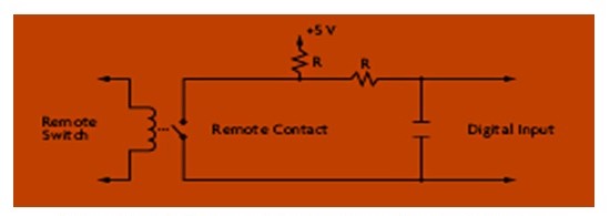
Digital Inputs
The final basic part of the device circuit which should be considered is the digital input. This component can be considered an integral part of the device circuit because the signals both input and output are aimed at regular maintenance of the system.
Communication Protocols. The process of transmitting the data has its rules which are called the communication protocol. These rules are used to detect errors, transmit signals, present data through the communication channel. The current device can use two types of communication protocols: I2C or an Inter-IC bus and a JTAG or a joint test automation group. It is necessary to consider both types of communication protocols in order to understand differences in their operation.
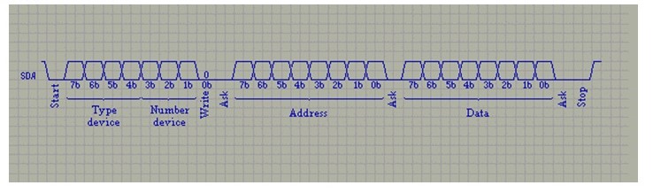
I2C is the first type of communication protocol that should be analyzed. It presupposes classical addressing, a 7-bit address space with 16 reserved addresses. This means a maximum of 112 addresses can communicate on the same bus. All I2C-compatible devices have a built-in interface, which allows them to communicate with each other on the bus I2C. This engineering solution solves many problems of coupling of different devices, which usually arise in the design of digital systems. It requires only two lines – the data line (SDA) and the line synchronization (SCL). Each device is connected to the bus; the software can be addressed by a unique address. At any given time there is a simple ratio of master/slave: key can operate as master-transmitter and the leading receiver.
The I2C bus allows you to have multiple presenters, providing a means to identify conflicts and arbitration to prevent data corruption in a situation where two or more leading simultaneously begin transmission of data in the standard model is provided by the transfer of successive 8-bit data at speeds up to 100 Kbit/s and up 400 Kbit/s in “fast” mode. A built-in chip filter suppresses spikes, ensuring data integrity. The maximum allowable number of chips that are connected to one bus is limited to a maximum bandwidth of 400 pF.
Standard I2C bus with transmission rates of 100 Kbit/s and 7-bit address exists for over 10 years unchanged. Standard I2C bus is universally accepted as the standard for hundreds of types of chips produced by Philips and other suppliers. Currently, the specification I2C bus extended in two directions: increasing the speed and expanding the address space to expand the range of newly developed devices. Introductory specification of the “fast” mode allows up to four times increasing data transfer rate up 400kBit/sec. The need for this “expansion” of the standard is required because of the need to transfer large amounts of information, and as a consequence, the need for increased bandwidth.
The next communication protocol which should be considered is the JTAG. It is a debugging system designed to be embedded in the CPU core debugging tools and their relationship with external debugging tools. An integral part of this unit is a five-wire diagnostic system which is a part of the standard IEEE 1149.1. It allows you to get a sequence of states of the conclusions debugged device. Through the existing port in the TAR, it can perform a limited number of debugging commands. There are two alternative implementations of the debugging systems: the so-called enhanced JTAG (eJTAG), proposed by MIPS Technologies, and the NEXUS interface.
Both communication protocols can be used in the automatic meter reading device in order to fulfill the commands and facilitate the transmission of signals from one unit to another. It is necessary to mention that the circuit would not work without one of the components which are considered basic for its operation. The smaller units contribute to the overall image of the device and help to make it reliable, upgradable, interoperable, scalable, and maintainable.
Projects Done in the Training Period
Vehicles Tube Counter. Vehicle counters are generally manufactured in two different types, as AEC is caring for its customers, and strives for the extended diversity of the manufactured product. Even though both types have their own advantages and disadvantages, they are adapted for acting in different environments. The first type of the counter is the Microwave Vehicle Counter that is based on the principle of locating vehicles passing through a definite point with the radio waves. Nevertheless, it is very ineffective if there are traffic jams on the road (when the counted vehicles are not able to move, or they move very slowly).
The second type is the counter based on the pressure level difference (Tube Counter). The pressure level is defined by the default pressure value, and the difference is achieved by the vehicle mass property. This type of counter is dug under the ground, and the two tubes of the counter are subjected to pressure, which vehicles produce passing over them. Thus, every pressure change originates the count up of the counter.
The main problem, which was faced by the customers, and what the manufacturers had to solve was the necessity to read the counting manually. AEC Company has undertaken to provide the customers with an opportunity to read the counting results distantly through SMS or via internet, for the users of the counters could control the results from a single control center or a webpage.
The problems arose when it was found that the counters are 20-years old, and there is no documentation for them found. Consequently, there was a strong necessity to study them from the very beginning and study the principles of counting, as well as the opportunities of passing the data distantly to the control center. Thus, the system of sending and receiving codes should be developed for the proper technical performance of the counters, as the proper and full understanding of the codes is crucial for sending data through the required data transmission protocol, which should be developed for this project.
Procedure. The main aim of the technical procedure is to analyze and realize the principles of forming codes for each counter, as these codes will be sent through the GSM protocol. The further step of data processing is automatic analysis. Thus, the devices will be linked with the RS-232 computer, and then the Hyper Terminal is aimed at catching and analyzing the data, received from the counters.
The next step is the code analysis, which starts with the process of parameter exchange. Thus, time, date and number of counts are transferred from the device to computer. Any changes in the data code are noted by the computer, and the required system of code changing is defined, for that further data could be read properly. Finally, the protocol document with the code analysis and code changes will be sent to the software analysis team, who will program the GSM engine, which will be responsible for reading and extracting the required information from the counters.
Environmental data Sensors. The key environmental data which should be analyzed is the temperature and humidity, which may influence the precision of the pressure counting. Thus, the project of data processing improvement should be outlined with the help of the HVAC systems (Heating, Ventilation, and Air Conditioning systems). Currently, these systems are known as climate control, and are widely implemented in various offices and manufacturing lines for creating more comfortable working conditions for the personnel. On the other hand, climate control maintains the required temperature and humidity level for the proper manufacturing, as numerous pieces of equipment requires precise climate regimes. Thus, the electronic industry, which is engaged in manufacturing the vehicle counters, analyzed in this paper, requires precise maintenance of climate control, as the extensive humidity may damage the electronic schemes of the equipment. Thus, the HVAC systems appear to be very popular, as they are simple for installation, the maintenance costs are low, and the operating costs are essentially lower, in comparison with the other control systems.
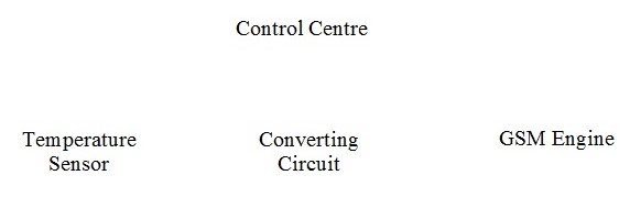
As for the project of the vehicle counters, it should be stated that the temperature sensor, installed in these counters, is capable of reading the temperature of the environment between 0-50 ˚C, and it should be always connected to the GSM engine. Therefore, it was able to send the notification or alarm signal if the temperature changes, or if it exceeds the stated level. In light of this fact, the main aim of the GSM engine is to provide the control center with notifications on the changes in the temperature and humidity levels. Moreover, the GSM engine will be able to receive the requests from the control center for reading and sending the current data on the temperature and other climate data, if required. Thus, the GSM will send the request to the temperature controller, read the indications, and send SMS to the control center.
The entire diagram of the climate control system will be the following:
Work Procedure. The process of the installation of the environmental parameters control system is within the vehicle counters project is closely associated with the GSM engine datasheets. The sensor of the temperature, which is used in the project should be accurate enough for fixing all the minor changes of the environmental temperature. Originally, the range should be the same ‑ 0-50 ˚C.
Considering the technical parameters of the sensor, it should be emphasized that the output signal of the sensor is between 4 and 20 mA, and this range represents the set temperature range. The aim of the design, provided for the temperature sensor, is to convert the stated voltage rates, as the GSM engine is sensible to the voltage level between 0 and 36 V. Thus, the converter, adjusted between the temperature sensor and GSM engine is responsible for the converting the data from the temp sensor, and avoid any voltage overload in order not to damage the GSM equipment.
Considering the voltage level, which represents the defined temperature set, it should be stated that the resistor value of the circuit converter should be selected for the results of the calculation values and data processing were within the frames of the selected voltage range. Thus, every temperature level could be assigned for the specific voltage value, and the maximum temperature level did not exceed the maximum voltage level, permitted for the GSM engine. Finally, the GSM engine is aimed at converting the received electronic signal to a digital signal, which is suitable for the transmission to the control center, and the data is deciphered in the control center in accordance with the properly proceeded and stated datasheet, and formula, which is given in the GSM document.
Design Procedure. To start working on the project, we need to select the proper value of the conversion resistor. Originally, the universal resistor value is 1.6 k Ω, as this value provides a wide range of voltage with the current values of the voltage. Thus in accordance with the following formulas:
- 4 mA x 1.6k Ω = 6.4 V
- 20 mA x 1.6k Ω = 32 V
It should be emphasized that the selected voltage values provide the proper voltage range, and in accordance with the results, 1V equals 1.953125 ˚C. Thus, the maximum value of the voltage level is 32V. From this perspective, the resistor value of 1.6 k ohm restricts the required voltage range, for the GSM engine was not subjected to overloads, moreover, it provides low energy consumption, as the total voltage is low enough.
After the resistor value has been selected, the table of values should be created. Thus, the voltages have their temperature equivalents, and, there is a strong necessity to calculate the real values, and compare them with the accurate values.
Table 1 : a sample of the values table. Table of temperatures and Voltage Levels
This table represents the values of temperature (the 1st column), and the voltage levels (the 2nd column). The formula for calculating these values is the following:

The ADC value (the 3rd column) represents the digital signal value, which is converted by the GSM engine for the further transmission to the control center. The equation which is used for this calculation is the following:
![]()
After that, the conversion of the ADC values for the GSM engine is equal with the temperature levels, and the matters of the digital signal, which is sent by the means of SMS. Therefore, the software team undertakes the further step of the process processing. The program code, which will be used for deciphering the received data will be based on the following formula:
![]()
Programming the GSM Engine Process. Previously to the beginning of the programming process, the algorithm chart should be provided for avoiding any mistakes and avoiding any loops and unnecessary cycles in the process of data processing.
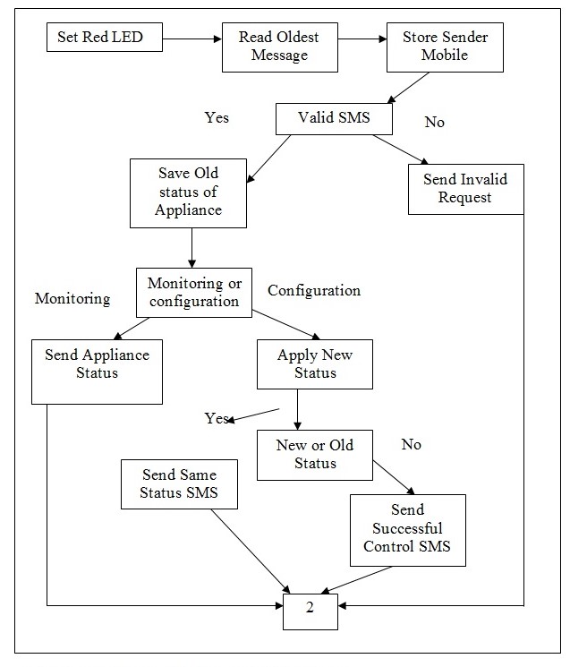
The program was written in Python, and then implemented for the GSM engine.
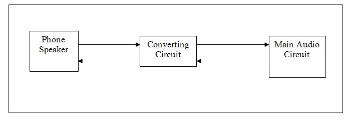
Speaker Project. The original idea of the project is closely associated with the implementation of the special speakers that will be sending and receiving inputs and outputs of the analog signal. The only problem, which arises here, is the necessity to connect these speakers to the audio circuit, which is compatible with differential inputs and outputs.
Considering this fact, the following task, which was faced by AEC is the elaboration of the circuit, that will be able to convert the single-ended input to differential output.
In accordance with the chart of this process, it should be emphasized that the two-way conversion should be available for the increased compatibility
Procedure. In order to start the implementation process, research on the converting principles should be performed. Originally, lots of designs are available, consequently, they should be adapted for the existing project. Selecting the proper design, such parameters as output signal quality and voltage level were considered. Finally, two of the most effective solutions were found and defined for the further implementation. The first choice is based on the Differential OP-AMP scheme. Thus, the easiest design for the required equipment is the following:
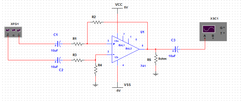
The design for the OP-AMP, represented in the scheme requires the precise adjustment of the values of capacitors. Originally, the values should be selected by this principle:
- R1 = R3; R2 = R4
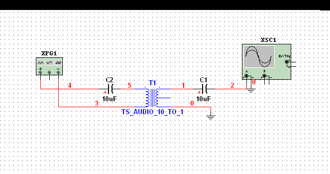
The second circuit of the scheme was created after the replacement of the audio transformer. Originally, since the OP-AMP transformer has been replaced, the differentiation principles appeared to be changed. Additionally, there is another merit of the design, as this scheme provides an opportunity of changing the input impedance to a standard value, depending on the matters of the standard input on the audio transformer.
Thus, the transformer is included in the scheme for converting the single-ended input, thus, the capacitors are used for protecting the microphone from overloads, and the resistors are used for powering up the microphone.
The following scheme represents how the differential output is linked with the transformer, thus, the single-ended output is achieved as a result.
Consequently, to select the best scheme, these two variants should be compared. The following table is aimed to analyze and compare both variants.
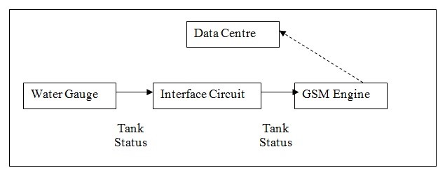
Water Gauge Project. This tool is required for measuring and improving water systems. The main aim of these systems is to ensure the users that water supply will not be stopped in their houses, thus, improving the comfort levels of the people, who have acquired this system. The main idea of the project is to connect the water measuring system and the SMS informer, for the GSM engine could send the notifications to the Control Centre. Thus, the water tank status will be always monitored without the participation of the user. If the tank is empty, or close to empty condition, the Control Centre contacts the customer, and delivery is performed.
The AEC Company was asked to design a special equipment, which will be controlling the water levels in the tanks, and then inform the delivery service on these levels by the means of SMS. The entire flow of the process is the following:
Procedure. The entire design process of the gauging equipment is simple enough, nevertheless, the GSM engine requires some improvements. The output signal is provided by the three contact wires, which are responsible for measuring the water levels. The GSM engine is programmed for sending and receiving the coded signal in the case of necessity.
The three contact wires are located on different levels of the tank, thus, when all the three contacts are circuited, it means that the tank is full. If the water level is low (the tank is close to empty), only one wire will be circuited with the ground.
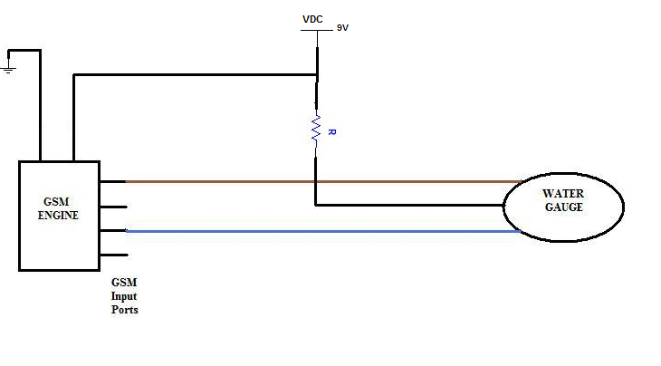
The main idea of the project is the connect a 9V power supply to the ground through a resistor of precisely defined value. The program, which defines the GSM engine behavior will have to check the voltage on the wires, define the situation (water level), and send the notification.
Data Collection Unit. The data collection unit is the system, which was implemented by AEC Company for collecting the measuring data from more than 30 indicators. This unit entails five main parts, which are aimed at controlling, measuring, coding and sending the received data. These are the following:
- Microcontroller
- Power Supply
- Modem
- GSM engine
- Reserve power supply
The microcontroller may be compared with the brain of the device, as it entails the software filling of the unit. Power supply and reserve one are responsible for powering the schemes of the data DCU.
The modem is the third part of the unit. It analyzes the received data and sends the encoded signal to the GSM engine. Finally, the engine sends the signal through GSM or GPRS to the data center.
The fact is that, these are the most sensitive and complex products of the ACE product line. It has to pass numerous tests and measurements for being shipped to a consumer, and the complexity is emphasized by the fact that only 300 items have been manufactured and shipped to customers. Up to 30 of the total amount of the manufactured units failed to pass tests.
Procedure. The main task was to check and define the problem of the DCU gadgets, providing a report on the matters of the failures of the units, which were manufactured, and failed to pass the manufacturing tests.
First, the unit should be connected to PC, which analyzes the device, and after that, the unit is tested again, as often problems appear in the GSM engine part. If no problems were found, the unit is disassembled and the accuracy of manufacturing is checked. Then, the downgrade to the IC level is performed, in order to check this level for damages. The continuity test is aimed at checking the connections between various boards and blocks of the circuit schemes.
Finally, a report is provided to the technician, who should check and fix the problem.
Conclusion
In general, the practice at the Advanced Electronics Company was rather productive and educative. Much information has been evaluated, and personal understanding of the issues that AEC deals with was considerably improved. The major aims of this organization are to present effective services, devices, and goods to its customers and make all this available to people in different countries for different purposes. AEC is characterized by unbelievably fast growth and taking a leading position in the military, industrial, and telecommunications markets. The success of the company is promoted by well-coordinated work of specialists, who are always ready to enlarge their level of knowledge and maturity.
AEC is improved by numerous ways like proper organization of departments that are responsible for different spheres of work, presence of ESD course training that helps to organize and control the work with sensible devices, in-circuit, function, or continuity tests. In particular these types of tests are necessary for improving TADS/PNVS system, which is still at the stage of development.
The development of automatic meter reading is considered to be the main part of my practice. This technology helps to control data from all metering devices automatically, and this possibility considerably improves and facilitates the work of all departments. Though current technological development requires new approaches and demands, the idea to use these meter readings remains to be urgent because it is able to unite numerous functions that are performed over meters.
The possibility to focus on such projects as temperature and humidity sensor, water gauge, or speaker project allows to develop and to improve personal skills and awareness about the subject. Each project has its own peculiarities and its effects on general work. This is why it is necessary to think over a separate way of how to comprehend the essence of these projects and their effects on AEC work. This organization has many promising projects, and its development remains to be crucial nowadays.
Works Cited
Military. Advanced Electronics Company, 2005. Web.