The ideal design for a manufacturing principle for the James G Carrick & Co. Ltd. should be centered on the concept of a compact manufacturing system. Compactness in a manufacturing system implies the acquisition of machines that are able to multi-process and multitask. For instance, James G Carrick & Co. Ltd. could acquire a single machine that triples up as a flanger, beader and reducer or a single machine that can do at least two processes. The machines themselves have to be of a compact structure and in addition be able to produce a single output for a given process.
The idea behind a compact manufacturing system is that the company shifts from a very spread manufacturing system to a compact one that has reduced movement, manual intervention and less total set up time. For instance, by acquiring a compact machine line that can perform all three processes – beading, flanging and reducing – the company will no longer have to move steel cylinders manually through these stages but more effectively have a single machine to do it, a machine, which has reduced movement and is able to handle more than one cylinder at an instance.
The concept of compact manufacturing system is advanced by companies like Atlanta Grotnes, Oswell Engineering and Shanxi Universal Machinery Plant who develop steel container and drum manufacturing equipment not as individual machines but as a single unit called a line that is able to carry out more than one process. For example, a single line is able to do seaming, welding, beading, flanging, corrugating, reducing, drum or container testing and drum finishing that is painting. These lines come with a host of other advantages that include safe operation and easy maintenance.
Besides, the ideal design for a manufacturing principle for the James G Carrick & Co. Ltd. should augment the concept of an automated manufacturing system. Having in mind that one challenge that James G Carrick & Co. Ltd. is facing is the level of manual involvement required in its manufacturing system and that they are interested in coming up with a machine principle that requires less total set up time. Then, automating its manufacturing system will aid in addressing this challenge. Automation involves the running of manufacturing machinery through programmable controllers and one of its many advantages is that in case a change in the manufacturing system is required, the machines are not the ones that are changed but it is the set of instructions being input into the controller.
Another advantage of an automated manufacturing system is the high speed in which instructions that are aimed at changing the manufacturing system are implemented. An automated system does not only address machine operations only but also manages the transport and feeding mechanism of a plant. Oswell Engineering and Shanxi Universal Machinery Plant are two companies that have devoted their efforts to not only include the development of a compact manufacturing system but an automated one as well.
An automated manufacturing system has negligible total set up time because everything in the system is put in place for control by the programmable controller. Thus, the only time that needs to be checked is booting time associated with the programmable controller. Many companies design programs or software for automating a manufacturing process. Examples of such software and the companies include CATIA (Dassault Systems), Cimatron (Cimatron Group), Pw/E (PTC), NX (Siemens PLM Software), Mastercom (CNC Software) etc.
Such a design of a machine principle will enable the company to address its challenges that are clearly cut out for them. The company as noted that, first, a lot of manual effort is going into moving the cylinders, their use for manufacturing the containers and drums between the different stages of production and in particular their flanging, beading and reducing processes. Secondly, there is concern of the time taken to complete successfully the flanging, beading and reducing stages of their manufacturing process especially when they are required to meet customers’ specifications. Thirdly, the company is concerned with the rising production costs that are mainly due to the labor they employ to get their work done.
Subsequently, because of the high production costs, the level of production has also gone down. Fourthly, the company is seeking to expand its flexibility capacity as a move towards enhancing their ability to meet the specifications of different customers and to meet them in the time required. This should also be done in time. To respond to these challenges, the company for a start needs to adopt the design of machine principle discussed above that is a compact automated manufacturing system.
Manufacturing at the company is still done in the traditional manner, which explains why the company’s manufacturing process requires a lot of manual involvement. This traditional manufacturing principle implies the company’s use of outdated and old machinery. Of importance is the machinery that is used for flanging, beading and reducing. For the company to tackle the challenges facing it there is a need to replace their older and out of date machines with today’s hi-tech and sophisticated ones.
Therefore, the following three machines are the most recommendable for the company due to their efficiency and productivity. Being the latest machines, which are high tech, economical and efficient, it is by no doubt the machines will perform in accordance with the expectations.
Reducer
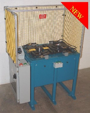
Below is Arm 3” – 10” Reducer machine. The reducer machine is automatic and it is designed in such a way that it produces very high quality tapered increasers/reducers. It is characterized by two workstations which make up the locking rib with each situated at both ends, one on the smaller end while the other is on the larger end. Only one person is required to operate the machine. In addition, the reducer machine can be got in various size configurations according to the demand.
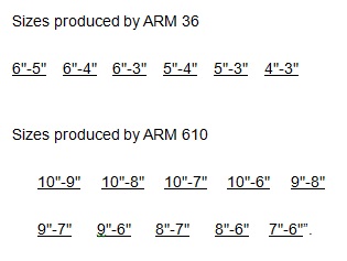
The ARM 36 type of the reducer is equipped with a set of tooling capable of producing different combination sizes in 1” increments ranging between 3″ and 6″ Ø. The ARM 610 reducer has a set of tooling capable of producing different combination sizes in 1” increments ranging between 6″ and 10″ Ø. Cleveland too and machine (n.d., p.1) states “Size changes take only 15-30 minutes to complete (depending on size).
Reducer Machine Productivity
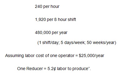
The machine’s cycle time to be precise is four seconds for all the sizes while its load time is approximated to be eleven seconds, which depends mainly on the speed of the operator. According to Cleveland too and machine (n.d., p.1) the technical parameter of the machine includes “Complete Reducers: 4 per minute
Technical features of the machine according to Cleveland too and machine (n.d., p.1) include “pre-programmed p.l.c. (Allen-Bradley MicroLogix 1200), proportional valves with precise ramping control of gear heads, easy-to-use operator interface, electrical: 230/460 VAC 3Ø, no air supply required, integrated lubricating system and hardened and heat-treated tooling”.
The machine is equipped with safety feature, which include wire mesh frame, yellow guards, emergency stop button and warning labels.
Beader
The machine presented below is quite preferable as a beading machine that the company should contemplate using. The beading machine is designed in such a way that it has a shape, which enables it to reinforce beads on specific arbitrary blanks shapes and over the entire sheet metal tables.
The parameter of the machine is presented on the table below
Source: Jack-aiva. (n.d.). Beading machine. Web.
Jack-aiva. (n.d., p.1) states, “This is used for reinforcing whole plates or parts of shaped pieces from sheet metal. Reinforcement inhibits vibrations in HVAC ductwork. It is manufactured in many designs, differing in the maximum width of the plate or profile of the crease”.
This particular beading machine is hailed for its ability to produce very strong reinforced duct panel characterized by cross bead patterns, which are quite attractive. The table below presents main parameters specification of the machine.
Source: Jack-aiva. (n.d.). Beading machine. Web.
Flanger
This particular flange machine is the most suitable for the company to use due to its efficiency and productivity. The machine is able to process flange diameters ranging from 250mm to 3000mm.
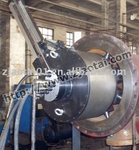
This particular flange machine is well researched and designed suitable for long distance pipe operation. Going by the technical parameter of the machine, it is more efficient and profitable to use. Alibaba (2010, p.1) on presenting the facts on the technical parameter of the flange machine states “Rated Pressure: P=20Mpa Rated flux: Q=25L/min
Hydraulic Motor: N=160r/min Output torque: M=320N. M.
Electric Motor Power: N=7.5KW Electric Motor Rate: N=1450r/min
Timing range: 0-30r/min”. It is therefore evident that the machine is not only efficient but also economical.
Alibaba (2010, p.1) further states, “Flange Facer is an internally mounted machine with a durable construction. Machining sizes range from 50mm up to 2000mm or more. It has hydraulic unit with low heat and low oil consumption and hydraulic or pneumatic drive, wide use range”.
Flange machine is available in different models, which have different clamping and working range as shown below.
Source: Alibaba. (2010). Flange Machine.
Other machine in the market is Atlanta Grotnes’s high-speed flanger machine, which as the name suggests is used for flanging. Atlanta Grotnes’s high-speed flanger incorporates a tooling change arm that allows for fast changing of the tooling used for tight head and open head drums (Atlanta Grotnes Machine Company, n.d.). Another attractive feature of this particular machine is the motorized length adjustment, which significantly lessens the setup time when moving from tight head to open head forming (Atlanta Grotnes Machine Company, n.d). The flanging process involves the folding of one or both ends of the steel cylinder as used in the making of the containers and drums.
Acquisition of such hi-tech machinery is only the first step; the company needs to follow it up with the installation of a CAD/CAM system as well as quality improvement process. The benefits provided by the individual machines coupled with the benefits that are associated with a CAD/CAM system supersede the challenges the company is facing and even see them as opportunities (Mitchell & Kowalik, 1999).
Another machine available in the market is the Combined Spin Flanger/Beader SBV 400 (Anonymous, n.d.). As the name suggests the SBV 400 is a single machine in which both flanging and beading process can be done. The machine has 14 heads, six of these are in the flanging station and the rest are in the beading station. Taking into account, these allowances for beading and flanging the SB 400 comes in compact design. The flanging station of the SB 400 is designed to operate exclusively under the proven spin flanging principle. The beading station in addition to hosting the beading heads also contains two mandrels, one on the inside and the other on the outside. The design of the SB 400 is vertical and allows for high levels of precision. It is due to these strengths in its design that the SB 400 is recommended for use with very thin double reduced tinplate in DR quality.
The table below shows specifications of the Combined Spin Flanger/Beader SBV 400.
From the table, the Combined Spin Flanger/Beader SBV 400 can be used to construct steel drums and containers of varying diameters and lengths. The SBV 400 can additionally operate at two different production capacities, in the first capacity it can flange and bead 80 to 330 steel cylinders per hour and in the second capacity, it can handle 40 to 65 steel cylinders per hours.
Another machine for steel container and drum manufacturing that is available in the market is the Steel Drum Making Equipment from Shanxi Universal Machinery Plant (Focus Technology Co., Ltd, 2010). The machine in itself constitutes a number of machines that are arranged to make line for either drum body production or painting. The machine can cut; weld, form and seam steel as well produce drum bodies as well as painting. The drum production line contains flanging, corrugating, beading, seaming, welding and leakage testing machines.
The machine is automated through a programming controller thus there is reduced manual intervention required in the manufacturing process. The machine uses a hydraulic system to drive its feeding and transportation mechanism. The machine is designed in such a way that it can be operated safely as well as allowing for easy maintenance. The design also allows for high levels of automation, low noise levels and a compact structure. Lastly, the machine is economic in its use of raw materials, that is, it is very restrained in its consumption of metal. The machine can produce steel drums of different capacities (100 – 220 liters) which are either open or tight and can produce 2 to 10 drums per minute with the drums produced having a steel plate thickness of 0.8 to 1.2 mm (Focus Technology Co., Ltd, 2010).
Another machine that is available in the market is the Steel Drum Manufacturing Equipment from Oswell Engineering (Bierling, n.d). The drum production line comprises of a vertical beader, flanger and a 3-corrugation shaft automatic changer corrugators. Oswell Engineering offers a steel drum production line that is compact, simplistic, efficient and easy to maintain. In addition, the line comes with automation solutions drum end loading to seamer, drum end stacking and de-stacking (Bierling, n.d). Lastly, the line comes with a drum testing and finishing solution and it can produce 80 to 900 drums per hour (Bierling, n.d).
Now, of this machinery the two best for James G Carrick & Co. would be the above named three flange, beading and reducer machines. The reason for this is that these three machine lines very well capture to high levels of detail the concept of compactness and automation. By compactness the company shifts from a very spread manufacturing system to a compact one that has reduced movement, manual intervention and less total set up time. By automation, the running of manufacturing machinery through programmable controllers which helps the company reduce machine set up time and manual intervention needed in the manufacturing process.
In addition to these, their manufacturers have designed them in a way that that they can be operated safely, maintained easily and they use of raw material is economical (Treanor & Ollerton, 2005). Thus, by integrating, one of these machines productions at James G Carrick & Co. is expected to rise and costs associated with the production process to flop. Other equally important features that these production lines have incorporated are the drum testing and drum finishing automated solutions. These solutions will make it easy for James G Carrick & Co. to easily finish and test the products at low costs and with little manual intervention. Such production lines are the methods of choice today for companies involved in steel drum and container manufacturing.
In order for the company to make changes in the already existing machinery, it is important that they understand the concept of quality improvement. Continuous quality Improvement refers to the formal approach applied in analyzing performance as well as improving it (Duke University Medical Center, 2005). The Plan-Do-Check-Act (PDCA) system and the Failure Mode and Effect Analysis (FMEA) are two underlying concepts of continuous quality improvement (ASQ, n.d.).
The abbreviations PDCA stand for Plan-Do-Check-Act. According to the article Lee, et al. (1999), the American Statistician Walter Shewart came up with a four-phased conceptual framework for flashing out a problem within a system. This was Stewart’s Plan-Do-Check-Act (PDCA) analytic and systematic procedure. Stewart’s Plan-Do-Check-Act cycle is designed in such a way that by completing the cycle a problem-solver has dealt with a single problem. Thus, to root out a second problem in the system a problem-solver will have to complete the cycle a second time and so on. Stewart’s Plan-Do-Check-Act cycle can be used as a utility tool in planning where actions are meant to be practical and are without fail plan sensitive. A plan of such a nature should yield progress as well as register an improvement in results. Stewart’s Plan-Do-Check-Act system is also a useful tool in team building.
This is because, first, the system provides an organization with a means through which it can monitor the progress of the solutions it has adopted (Crow, 2002). Secondly, it additionally provides an organization with the means to choose the most feasible solution form set of alternatives or options. In Stewart’s Plan-Do-Check-Act cycle, the planning stage involves carrying out two tasks; the first task is to identify the fault issues. Once you have accomplished this task the next will be to device remedial interventions to be adopted by an organization so as to fast track its operations.
The second stage of the Stewart’s Plan-Do-Check-Act cycle is the Do stage. In this stage, a solution is implemented in small doses while at the same time weighing the results obtained from trying out other different alternative interventions to every problem (Sarma, n.d). A problem-solver must be keen to ensure that the process of taking measurements does not come into the way of the systems operations. Another task to be undertaken in the check stage will be to determine the efficiency of each remedy available.
By doing this a problem-solver can determine the merit associated with each of the available remedies. The fourth stage in Stewart’s Plan-Do-Check-Act cycle is the Act stage. It is at the Act stage where a full fledge adoption of the merited remedies from the Do stage happens. Such a comprehensive adoption of remedies may result into adjustments in the different levels of operations in an organization. If at the Do stage, the pilot is not effective then go back to the planning stage to formulate new solutions and go through the cycle again. As pointed out above, if the system is plagued with several problems then a complete implementation of the cycle should be done on repeated occasions, a single implementation of the cycle should address a single problem.
As the company realizes flexibility, it is important in measuring performance and it provides an aggressive means of persuading customers to buy your product or utilize your services. These create positive links between customer satisfaction, employee quality life at work and a superior product (Silva et al, 2009). Flexibility in its designs to meet customer requirements is another challenge that James G Carrick & Co. Ltd. is facing (Dovach, n.d.).
The ideal design for a manufacturing principle that can assist them in addressing this challenge and that will require less total set up time is one that integrates an automated compact manufacturing system with an advanced designing mechanism. Search an advanced designing mechanism is only available through computer technology and is such that a designer can simulate a detailed, 2-3 dimensional model of an actual physical object using advanced computer software and hardware. The advantage of computer designing technology is that it allows a designer to view a design at any angle as well as enabling the designer to manipulate the design in various respects (McLean, n.d.).
The manipulation of the design may include the exploration of different colors on it, trying out different textures or simply doing a review of the design. Other benefits of this technology are the low cost of product-development and the shortened length of the design cycle. Once design is agreed upon it is stored electronically and/or fed – through digital technology – to the automated compact manufacturing system that implements’ the desired changes to create a finished product that resembles to a high degree the electronic design (WiseGEEK, 2010).
According to BusinessDictionary.com (2010), the system will also equip the company with high levels of precision in their end product. This arrangement of work guarantees customer satisfaction and ensures that the raw materials are used economically and that the company’s energy is utilized efficiently. In addition, the production system is clean since it minimizes and prevents waste production (Clift, 2001). In today’s world, it is important that your product is seen to be green, that is, it shows a concern for the environment (Manahan, 2005).
Thus, the company can aggressively attract more customers while at the same time it reduces the cost of production. Modifications to a design are not arduous to carry out because of physical involvement but are simply taken care of by the computing art of programming. Computerized designing has evolved and replaced traditional modes of drawing and modeling of designs clearly becoming the tool of choice for designers, engineers and architects (CADlogic, 2010).
References
Alibaba. (2010). Flange Machine. Web.
Anonymous, [n.d]. The Combined Spin Flanger/Beader SBV 400. Web.
ASQ, (n.d.) Failure Modes and Effects Analysis. Web.
Atlanta Grotnes Machine Company. (n.d.) High Speed Flanger. Web.
Atlanta Grotnes Machine Company. (n.d.) Beaders and Corrugators. Web.
Atlanta Grotnes Machine Company. (n.d.) Automatic Seamer. Web.
Bierling, P. (n.d). Global Business Support. Web.
BusinessDictionary.com. (2010) Prototype. Web.
CADlogic (2010) CADlogic. Web.
Cleveland too and machine. (n.d.). Reducer Machines. Web.
Clift, R. (2001) Clean Technology and Industrial Ecology. UK: The Royal Society of Chemistry.
Crow, K. (2002) Failure modes and effect analysis. Web.
Duke University Medical Center. (2005) What is quality Improvement. Web.
Focus Technology Co., Ltd. (2010) Steel Drum Manufacturing Equipment. Web.
Jack-aiva. (n.d.). Beading machine. Web.
Lee, H., Shiba, S., Wood, C., Walden, D. & Bergonzi, C. (1999) Integrated management systems: An aractical approach to transforming organizations. New York: John Wiley & Sons.
Manahan, SE, (2005) Environmental Chemistry, USA: CRC Press.
McLean, C. (n.d.) Computer aided Manufacturing System Engineering. Web.
Mitchell, E, & Kowalik, T, (1999) Creative Problem Solving. Web.
Sarma, A.D. (n.d.) FEMA in action Integration of Process of FMEA in a software project management. Web.
Silva, B., Filho, S., Ceccarelli, Z., Anjos, B. & Fesz, M. (2009) Integrated product and process system with continuous improvement in the auto parts industry. International OCSCO World Press, 34(2).
Treanor, K.M. & Ollerton, B. (2006) Process failure mode effect analysis CA/PA-RCA Advanced tool. Northrop Grumman Corporation. Web.
WiseGEEK, (2010) What is computer Aided Manufacturing (CAM)?. Web.