Objectives of the system
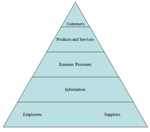
The system under discussion should perform the following operations: registration, authentication and authorization of external and internal users. It should serve the interests of such stakeholders as customers, employees of the company, suppliers and related organizations. With its help, clients must be able to get access to the resources of the website in order to search for a product, make orders, specify the requirements for the purchase and leave their feedbacks. In turn, the personnel of this firm will need to use this application to confirm orders with suppliers, register new products, bring the data up-to-data and so forth. On the whole, this work system framework will constitute such components as
- current and potential customers;
- products and service;
- usiness processes;
- information and
- workers and suppliers (please refer to the appendix to see visualized presentation of WSF).
The main purpose of this application is to ensure that various participants can exchange information with one another without any disruptions or delays.
Description of the system
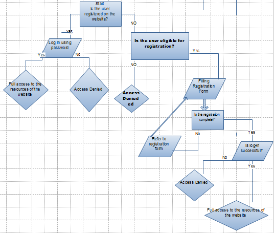
At first, it is of the crucial importance for us to describe the functioning of the system. Overall, it is based on the so-called IF-Then algorithm, which means that it performs a certain action under specific conditions. The first step that should be made is to determine whether a visitor (customer, employee or supplier) has been registered on the website. Afterwards, there can be two possible options: 1) if he or she has been put on the list of authorized users, the system would require password in order to provide access to the resources of the website; if not the visitor will have to fill the registration form: name, e-mail, account, and so forth. At the point, when the registration has been completed, the visitor will need to log-in. Provided that the client inserts correct password, he is automatically allowed into the web-site. Yet, there can be other scenarios; he may not fill all fields in the registration form: then the system would refer him to this form once again.
We can observe that textual analysis of the programs logic is rather inadequate because on its basis we are not able to mark out specific algorithms for problem-solving. Under such circumstances graphical modeling (especially UML (Unified Modeling Language)) is the best strategy for object-oriented programming. It should be borne in mind that this application must require log-in information for each page of the website even if users enter URL address directly. We can argue that one of the most important aspects is to develop a decision tree for the system. For this purpose, a flowchart is most helpful as it depicts the logic of the program as well as its decision-making techniques (Please refer to the appendix to see the flowchart for the system. Picture 2) (Ambler, 113).
The construction of flowchart is beneficial in many ways: 1) first, it can be used for the development of programming code. Secondly, this model can be adopted for the creation of similar applications. If the flowchart reflects all the logical steps of the application, it will significantly facilitate the process of development.
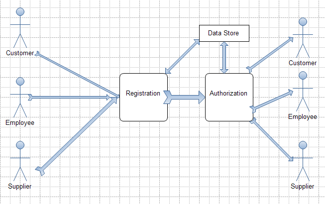
Another issue which should not be disregarded is the flow of data. This software solution can be viewed as an open system because it receives inputs from the environment (clients, personnel and partners), processes this information, and responds to the environment. In this particular context, the term environment can be substituted by such notion as external agent or actor (Curtis & Cobham, 554). The data flow model includes the following actors and processes:
- external agent;
- registration;
- data store (the unit where personal information of recorded and kept)
- authorization and authentication and
- feedback to the actor (Please refer to the Appendix, Picture 3 in see Data Flow Diagram (DFD).
The key task of DFD is to identify outside sources of data, the key processes. This diagram aims to describe the interactions of the system with external agents.
In addition to that, we need to determine whether this application will memorize log-in information or not. On the one hand, it is very convenient for the users when they do not have to insert password many times: currently many web-browsers such Opera or Firefox can retain them. Nonetheless, this feature also constitutes a significant threat to the security of the companys data as some users, especially clients can access the Web site from various entry points. It is not advisable to leave log-in data on PCs of unauthorized users. This is why we suggest that access code must not constitute more than six symbols. It may alternate both letters and digits. Yet, for the sake of privacy the application must demand these data in each case of entry.
Furthermore, we must decide on the number of attempts, which a client can make in order to enter password. Very often the developers of software solutions believe that this number should be unlimited. Overall, such approach is quite understandable, because it serves for the benefit of the customers. However, we need to eliminate the possibility that a person will gain access to the system accidentally just by alternating different combinations of letters and digits. This is one of the reasons why the number of errors should be restricted to five or six. One may argue that this policy infringes upon the rights of the clients, but this is a minimum safety standard for such web-sites.
So, in this section we set requirements for the future registration and authorization system. Besides, we have developed a flowchart and DFD which show the logic of this application, its decision-making strategy, and interactions with external environment. Flowchart and data flow diagram will be of great assistance during UML modeling.
Design of the system: UML modeling
Usage
As it has been noted before, UML enables software developers to analyze and predict the functioning of software solutions. The first phase of the design is the construction of a scenario which would show the behavior of external agents and system. Use-case diagrams are the most effective method to do it. We need to draw two diagrams due to the fact that the system performs two tasks :
- registration;
- authentication and authorization.
These scenarios can be presented in the following format:
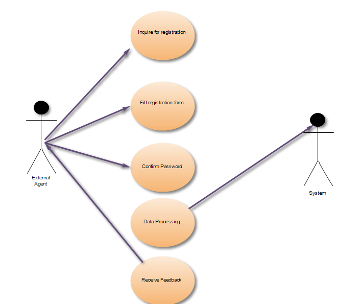
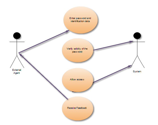
The objective of these diagrams is to illustrate various situations in which the system is going to be used. Additionally, this picture identifies the chief processes within application. Nonetheless, it should be taken into consideration that use case alone is insufficient for the creation of an efficient UML model. The problem is that this diagram focuses only on functional aspects of the system, excluding other important elements like timing, platform, interdependence of units etc.
Therefore, we need to enumerate main constituent parts of this solution. This can be done by drawing a component diagram as it demonstrates how the elements of the system are connected with one another. In particular, we need to determine whether they are dependent or independent from each other; or if they can be related as a part and a whole. All these aspects can be displayed in the graphic.
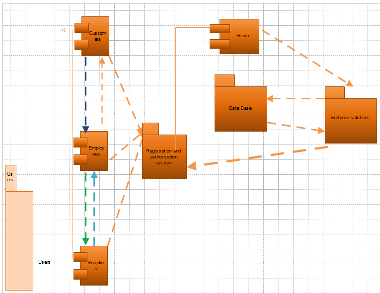
So, this diagram enables us to see the way in which the elements of system are intertwined with one another. At first, we can single out closely two associated pairs:
- employees and customers;
- personnel of the company and suppliers (or any other partners).
Additionally, it should be pointed out that that the system starts its operations only when it receives an inquiry from the server. Afterwards, it sends this query to the database. It juxtaposes the information, stored at the database with that one given by the visitors or users. The decision is based solely on the results of this comparison. Still, we can gain better understanding of the operations and processes if we draw a sequence diagram, which depicts them in chronological order.
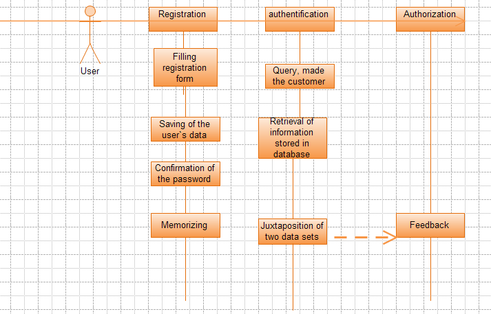
Judging from the sequence diagram, we can come to the conclusion that one of these processes is relatively isolated from others: it is registration. Subsequently, authentication and authorization can be considered as interconnected activities. The final process is utterly impossible unless the password, given by the user is qualified as valid. It should also be mentioned that the efficiency of this application relies on the functioning of database. Overall, sequence diagram is a very valuable tool for UML modeling as it gives a clear notion of the key processes and their stages. Nevertheless, it is also vital to correlate logical tasks, performed by the system with physical environment, in other words, hardware. Then there emerges a necessity to construct a deployment diagram.
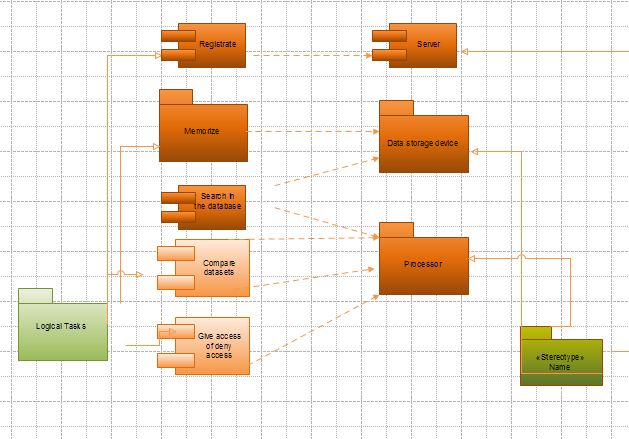
In the above diagram, we have tried to the functions of each physical unit:
- server;
- data storage device;
- processor.
On the whole, the performance of this software can be measured according to the following parameters:
- speed of processing queries;
- accuracy of data retrieval.
Finally, we should not forget about security of personal information like account number (as far as clients are concerned); stock level, demand and supply chain of the company and so forth. It has to be admitted that this application is not very demanding, but this company should not spare expenses on technologies as they are the main driver of their policy.
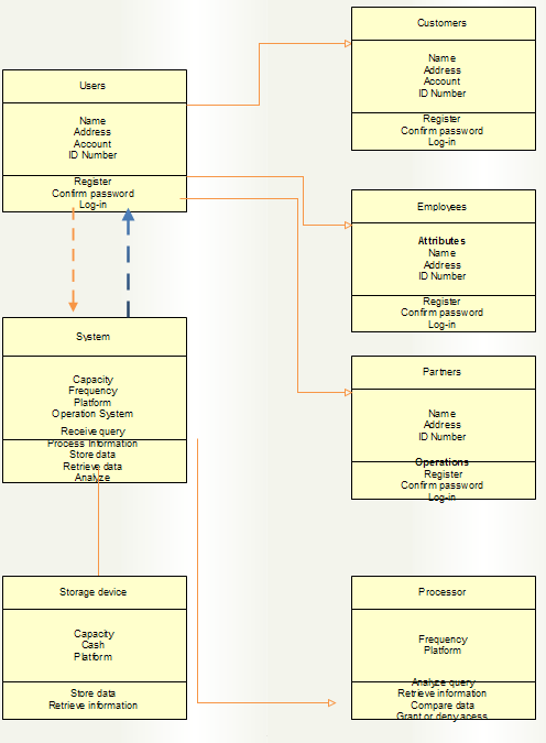
Class Diagram
Apart from that, while modeling any application, we need to divide it into classes and subclasses. It is critical to single out the major attributes of each class as well as its key operations. In the case, the key benefit of class diagram is that we would know exactly which type of information will be needed for this project. Secondly, this graphic will give better understanding of the hardware necessary for this system: namely its functional characteristics: like capacity, cash memory or frequency. Further information is presented below.
Conclusion
Thus, in this paper we have endeavored to describe and design a UML model of registration, authentication and authorization system. Various diagrams have been developed to present graphical version of this application. We may argue that a programmer must pay careful attention to such aspects as
- algorithms and decision making (flowchart);
- exchange of information between the system and external environment (DFD);
- the interactions between various constituent parts (component diagram);
- order of operations (sequence diagram);
- the relations between logical steps and hardware (deployment diagram);
- the attributes of each element within the application (class diagram).
Provided that the UML models take all these factors into account, they can be of great assistance during coding process. The adoption of E-business strategies may bring significant improvements into the performance of the firm because various parts of supply chain would be closely linked to one another. This system, which has been worked out, is only a small part of the companys website, yet, it is essential for the security of private information of customers, employees, and suppliers.
Appendixes
Works Cited
Ambler Scott. The elements of UML 2.0 style. Cambridge University Press, 2005.
Curtis Graham & Cobham David. Business Information Systems: Analysis, Design and Practice, 2008.
Fowler Martin. UML distilled: a brief guide to the standard object modeling language Addison-Wesley, 2004.
IBM Flowcharting Techniques. Web.
Stair Ralph & Reynolds George. Principles of Information Systems. Cengage Learning, 2009.